The resin trap is an essential safety protection device for water treatment ion exchange systems. It is specially designed to trap resin particles leaking with water flow, protect downstream precision equipment, stabilize water quality and prevent resin loss. It is widely used in power plants, pure water & high-purity water production, chemical, pharmaceutical and other industries.
Email:
xxhuaqing@126.comPhone:
+86 15936525232It adopts wedge wire screen elements for precise filtration:
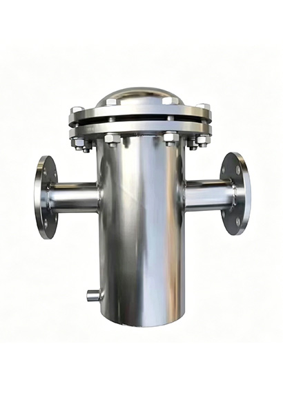
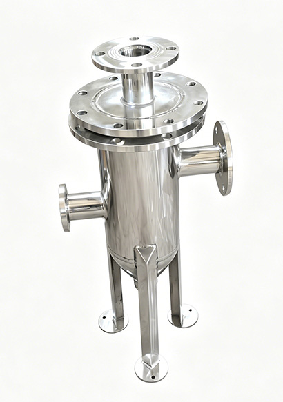
Installed on the outlet pipeline of ion exchangers. Water flows into the cylinder cavity through the lower side inlet.
Water passes through screen elements with an aperture of 0.1–0.5 mm (smaller than resin particle size). Resin particles are trapped by the screen, while purified water flows out from the top outlet.
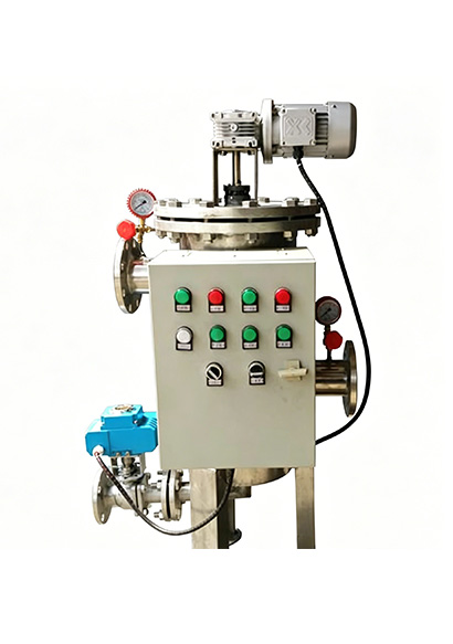
Trapped resin settles at the cylinder bottom. Backwashing can be activated by pressure difference or manual operation. Open the bottom drain valve, and reverse water flow discharges and recovers the trapped resin.
Equipped with sight glasses to directly observe resin accumulation inside for timely cleaning.
3.1 Main Structure
Cylinder: Cylindrical design, working pressure: 0.6–1.0 MPa. Optional materials: 304/316L stainless steel, rubber-lined carbon steel, fiberglass reinforced plastic (FRP).
Screen Element (Core Component): 316L stainless steel wedge wire screen, sintered mesh or basket screen. Gap ≤ 0.2 mm. Features: corrosion resistance, high mechanical strength, anti-clogging, long service life (3–5 years).
Inlet & Outlet: Flange connection (DN50–DN300). Standard configuration: side inlet & top outlet.
Drain & Backwash Port: Resin discharge port at the bottom, fitted with manual/automatic backwash valve.
Sight Glass: Combined with stainless steel and tempered glass for real-time internal condition monitoring.
Support Legs & Lifting Lugs: Facilitate installation and maintenance.
3.2 Standard Technical Parameters
Working Pressure: ≤ 0.6 MPa (High-pressure type: 1.0 MPa)
Working Temperature: 5–45℃
Filtration Precision: 50–100 μm (Suitable for resin of 0.3–1.2 mm)
Design Flow Velocity: ≤ 5 m/h (Prevent resin penetration)
Connection Type: Flange (GB/HG/ANSI standard)
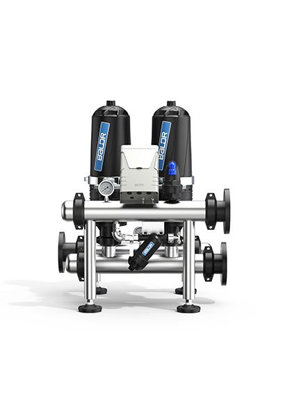
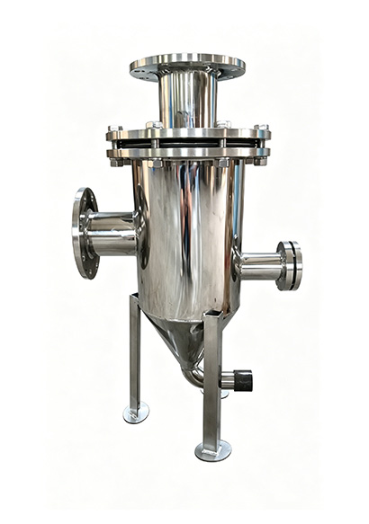
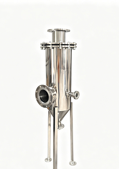
Vertical Straight Cylinder Type: Most widely used. Compact size, large flow capacity and easy installation. Applicable to pipelines of DN50–DN200.
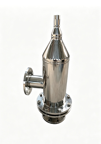
Y-Type: Compact structure with low flow resistance. Ideal for small-diameter pipelines (≤DN80) and low-pressure working conditions.
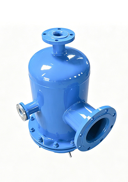
Basket / Horizontal Type: Suitable for large flow rates and easy disassembly & cleaning. Applied to pipelines above DN200 or working conditions with heavy resin leakage.
Wafer Type: Ultra-thin design, suitable for pipelines with limited installation space.
Power Plant Condensate & Boiler Feed Water: Trap resin after mixed bed to avoid boiler tube rupture risks.
High-purity Water for Electronics & Semiconductors: Protect RO membranes and EDI modules from resin contamination.
Pure Water Systems for Chemical & Pharmaceutical Industries: Guarantee outlet water purity and prevent resin particles from affecting product quality.
Circulating Water & Wastewater Treatment: Capture filter media such as activated carbon and quartz sand to protect downstream equipment.
High Filtration Efficiency: High-precision wedge wire screen achieves resin trapping rate ≥ 99%.
Corrosion Resistance & Durability: 316L material adapts to acidic and alkaline water, featuring long service life and low maintenance cost.
Low Pressure Drop & Large Flow: High open area leads to minor pressure loss, compatible with high-flow systems.
Flexible Installation: Available in vertical or horizontal mounting to fit various pipeline layouts.
Easy Maintenance: Simple backwashing operation. Reusable washable screen elements reduce replacement frequency.
Pipe Diameter: Match the on-site pipeline size (DN50–DN300).
Working Pressure & Temperature: Select cylinder material and pressure rating according to the maximum pressure and temperature of the system.
Resin Particle Size: Set screen gap to 1/2–1/3 of resin particle size (e.g., 0.2 mm gap for 0.5 mm resin).
Flow Requirement: Calculate cylinder diameter based on design flow velocity ≤ 5 m/h to avoid overload.
Water Corrosiveness: 304 stainless steel for normal water; 316L stainless steel for water with high acid, alkali or chloride ion content; rubber-lined steel or FRP for strongly corrosive media.
| Model | Caliber | D (cm²) | A (cm²) | B (cm²) | H (cm²) | Multiplier | Effective Area (mm) |
| MST-B1-25 | Diameter 25 | 89 | 160 | 260 | 480 | 7 | 36 |
| MST-B1-32 | Diameter 32 | 89 | 165 | 270 | 495 | 4.5 | 36 |
| MST-B1-40 | Diameter 40 | 108 | 180 | 300 | 550 | 4.5 | 57 |
| MST-B1-50 | Diameter 50 | 108 | 180 | 300 | 550 | 3 | 3 |
| MST-B1-65 | Diameter 65 | 159 | 220 | 350 | 650 | 3 | 3 |
| MST-B1-80 | Diameter 80 | 159 | 250 | 400 | 740 | 3 | 154 |
| MST-B1-100 | Diameter 100 | 219 | 310 | 470 | 880 | 3 | 246 |
| MST-B1-150 | Diameter 150 | 273 | 430 | 620 | 1175 | 3 | 487 |
| MST-B1-200 | Diameter 200 | 325 | 530 | 780 | 1495 | 2.5 | 786 |
| MST-B1-250 | Diameter 250 | 426 | 640 | 930 | 1810 | 2.5 | 1207 |
| MST-B1-300 | DN300 Threaded | 480 | 840 | 1200 | 2300 | 2.3 | 1654 |